
DIGITA CODE LOCK USING RFID
- Hiren Uthaiah M.S.
- Feb 5, 2023
- 6 min read

Updated: Feb 7, 2023
1. Introduction with Objectives
In recent times, mechanical locks are becoming more obsolete and the need for using digital locks continues to grow. Although they have proven to be reliable in providing security for many years, mechanical locks have become more vulnerable to thieves and intruders. Nowadays, burglars have learned how to easily manipulate traditional locks and have the tools needed to break them. Security is a prime concern in our day-today life. Everyone wants to be as much secure as possible. This is why more and more people prefer digital locks.
The purpose of this project is to create a micro-controller based Digital Code Lock with a RFID tag that serves the purpose of security. The microcontroller based Digital Code Lock is an access control system that allows only authorized persons to access a restricted area. An access control for doors forms a vital link in a security chain. The system comprises of a Arduino uno which acts as the brain. This system will allow you to preset a password and provide a RFID tag. The lock will open if and only if the RFID tag scanned matches and also the entered password matches the preset one. So, the access to enter the password is denied if RFID tag scanned mismatches. With these, the objectives covered are given below.
Password Based Access Control System using Microcontroller is used in the places where we need more security.
It can also used to secure doors, cell phones, computers and other equipments room.
The system will allow access to the person who knows the password and it will not allow access to unauthorized people. The system has an alarm to thwart the people who may try to break the protection barrier.
The authentication method used here is a four digit numeric code which is entered through the keypad. The code entered this way is then compared to the password stored in memory. The microcontroller continuously monitors the keypad for a match with the stored password. As and when there is a match the output line is enabled which can then be used to trigger an LED.
An LCD display is also used to display whether the entered password is correct or not.
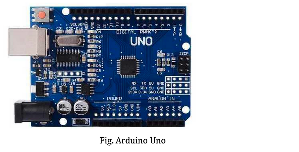
2. Description of Components 2.1 Board : Arduino The Arduino Uno is a low-cost, flexible, and simple-to-use programmable open-source microcontroller board that may be used in a wide range of electronic applications. It has 14 digital input/output pins (of which 6 can be used as PWM outputs), 6 analog inputs, a 16 MHz ceramic resonator, a USB connection, a power jack, an ICSP header, and a reset button. This board can operate relays, LEDs, Servos, and motors as an output and can be interfaced with other Arduino boards, Arduino shields.
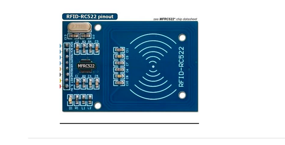
2.2 Peripheral 1 : RFID Reader A radio frequency identification reader (RFID reader) is a device used to gather information from an RFID tag, which is used to track individual objects. Radio waves are used to transfer data from the tag to a reader. RFID is a technology similar in theory to bar codes.
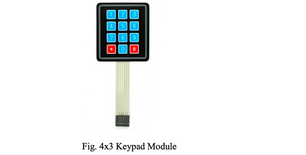
2.3 Peripheral 2 : Keypad Module The Keypad 4x3 features a total of 12 buttons in matrix form. A female 7-pin berg connector is provided for interfacing it with microcontroller units. An electrical wire connects all of these switches together. In most cases, there is no link between rows and columns. When we push the key, a row and a column fall into touch.
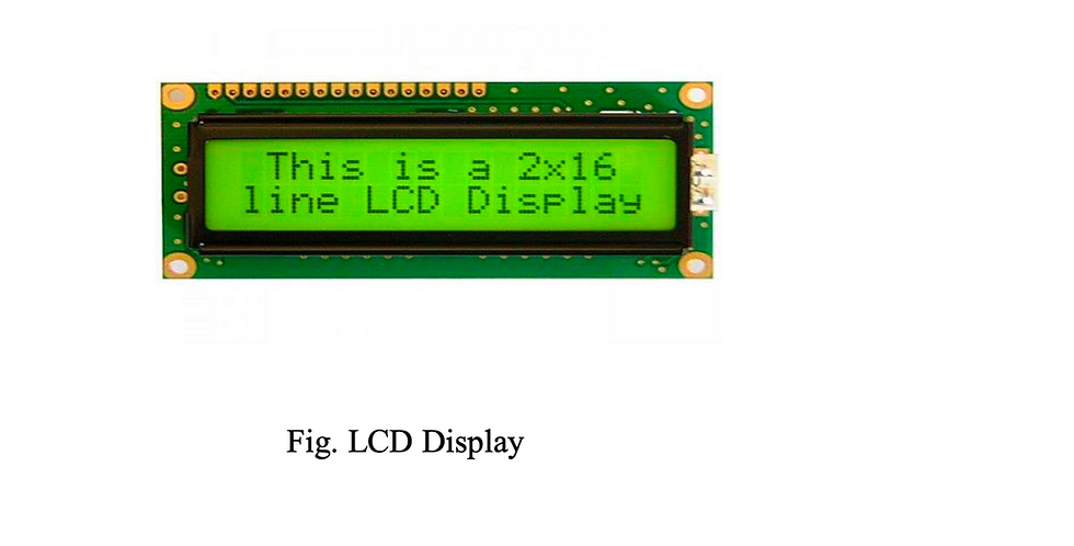
2.4 Peripheral 3: LCD Display The LCD screen is an electronic display module, it can be used in a wide range of applications. The basic module of the LCD is 16x2 LCD display and is very frequently used in various electronic circuits and as well as devices.
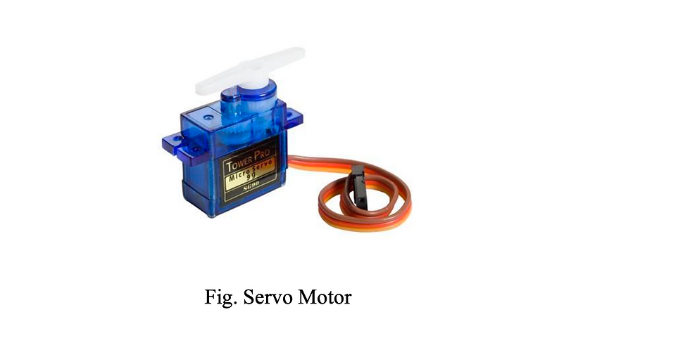
2.5 Peripheral 4: Servo Motor A servo motor is a simple electric motor which is controlled by servomechanism. When a DC motor is used as a controlled device in conjunction with a servo mechanism, it is referred to as a DC Servo Motor. AC Servo-Motor refers to a controlled motor that is powered by AC.
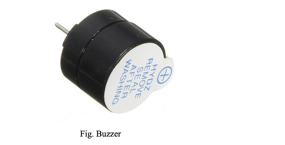
2.6 Peripheral 5: Buzzer A 5V Active Alarm Buzzer Module for Arduino is a low current audio signaling device, which may be mechanical, electromechanical, or piezoelectric. An active buzzer rings out as long as it is electrified. Typical uses of buzzers include alarm devices, timers, and confirmation of user input such as a mouse click or keystroke.
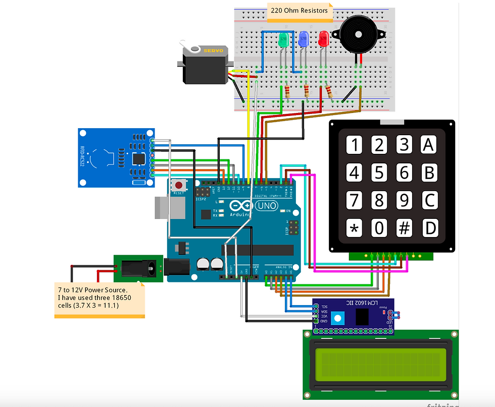
3. Circuit diagram with components
4. Code in ardunio/c/c++... with complete documentation (comments) // Include required libraries #include <MFRC522.h> #include <LiquidCrystal_I2C.h> #include <Keypad.h> #include <Servo.h> #include <SPI.h> // Create instances LiquidCrystal_I2C lcd(0x27, 16, 2); MFRC522 mfrc522(10, 9); // MFRC522 mfrc522(SS_PIN, RST_PIN) Servo sg90; // Initialize Pins for led's, servo and buzzer // Blue LED is connected to 5V constexpr uint8_t greenLed = 7; constexpr uint8_t redLed = 6; constexpr uint8_t servoPin = 8; constexpr uint8_t buzzerPin = 5; char initial_password[4] = {'5', '6', '8', '9'}; // Variable to store initial password String tagUID = "03 78 6D A7"; // String to store UID of tag. Change it with your tag's UID char password[4]; // Variable to store users password boolean RFIDMode = true; // boolean to change modes char key_pressed = 0; // Variable to store incoming keys uint8_t i = 0; // Variable used for counter // defining how many rows and columns our keypad have const byte rows = 4; const byte columns = 3; // Keypad pin map
char hexaKeys[rows][columns] = { {'1', '2', '3'}, {'4', '5', '6'}, {'7', '8', '9'}, {'*', '0', '#'} }; // Initializing pins for keypad byte row_pins[rows] = {A1, 0, 1, A3}; byte column_pins[columns] = {A0,A2,2}; // Create instance for keypad Keypad keypad_key = Keypad( makeKeymap(hexaKeys), row_pins, column_pins, rows, columns); void setup() { // Arduino Pin configuration pinMode(buzzerPin, OUTPUT); pinMode(redLed, OUTPUT); pinMode(greenLed, OUTPUT); sg90.attach(servoPin); //Declare pin 8 for servo sg90.write(0); // Set initial position at 90 degrees lcd.init(); // LCD screen lcd.backlight(); SPI.begin(); // Init SPI bus mfrc522.PCD_Init(); // Init MFRC522 lcd.clear(); // Clear LCD screen } void loop() { // System will first look for mode
if (RFIDMode == true) { lcd.setCursor(0, 0); lcd.print(" Door Lock"); lcd.setCursor(0, 1); lcd.print(" Scan Your Tag ");
// Look for new cards
if ( ! mfrc522.PICC_IsNewCardPresent()) {
return; }
// Select one of the cards
if ( ! mfrc522.PICC_ReadCardSerial()) {
return; }
//Reading from the card
String tag = "";
for (byte j = 0; j < mfrc522.uid.size; j++) {
tag.concat(String(mfrc522.uid.uidByte[j] < 0x10 ? " 0" : " "));
tag.concat(String(mfrc522.uid.uidByte[j], HEX)); }
tag.toUpperCase();
//Checking the card
if (tag.substring(1) == tagUID) {
// If UID of tag is matched. lcd.clear();
lcd.print("Tag Matched"); digitalWrite(greenLed, HIGH); delay(3000); digitalWrite(greenLed, LOW);
lcd.clear();
lcd.print("Enter Password:");
lcd.setCursor(0, 1);
RFIDMode = false; // Make RFID mode false
}
else {
// If UID of tag is not matched. lcd.clear();
lcd.setCursor(0, 0); lcd.print("Wrong Tag Shown"); lcd.setCursor(0, 1); lcd.print("Access Denied"); digitalWrite(buzzerPin, HIGH); digitalWrite(redLed, HIGH); delay(3000); digitalWrite(buzzerPin, LOW); digitalWrite(redLed, LOW); lcd.clear();
} }
// If RFID mode is false, it will look for keys from keypad if (RFIDMode == false) {
key_pressed = keypad_key.getKey(); // Storing keys if (key_pressed)
{
password[i++] = key_pressed; // Storing in password variable
lcd.print(key_pressed); }
if (i == 4) // If 4 keys are completed {
delay(200); if (!(strncmp(password, initial_password, 4))) // If password is matched { lcd.clear(); lcd.print("Pass Accepted"); sg90.write(180); // Door Opened digitalWrite(greenLed, HIGH); delay(4000); digitalWrite(greenLed, LOW); sg90.write(0); // Door Closed lcd.clear(); i = 0; RFIDMode = true; // Make RFID mode true } else // If password is not matched { lcd.clear(); lcd.print("Wrong Password"); digitalWrite(buzzerPin, HIGH); digitalWrite(redLed, HIGH); delay(3000); digitalWrite(buzzerPin, LOW); digitalWrite(redLed, LOW); lcd.clear(); i = 0; RFIDMode = true; // Make RFID mode true } } } }

Description:
The door locking system functions in real-time when the user puts the tag/card in contact with the reader.
The LCD display shows whether the card/tag shown is accepted or not and LED lights glows and the buzzer beeps.
If the tag/card is accepted, the system allows us to enter the passcode set earlier.
If the passcode entered matches the preset code, the servo motor is set to motion to illustrate the opening/closing of a door.
If the passcode entered does not match the preset code, the LCD display shows wrong password message, LED light glows and the buzzer beeps.
6. Applications of your model
The primary application of our model is to provide double security, one through the RFID and the other through the passcode.
Our model can be further upgraded and integrated to IOT and develop a smart door lock system.
RFID is a convenient entry method for offices. Most commercial office buildings today use some form of RFID magnetic door locks, especially for multi-tenant properties.
We can also utilize our model to provide solution for secure access of a space while keeping record of the user.
Our model provides a reliable and a consistent experience. Unlike other forms of traditional locks, our RFID locking system are double secure.
7. References
a) https://circuitdigest.com/microcontroller-projects/digital-code-lock-using-arduino
b) https://www.researchgate.net/publication/329835341_Internet_of_Things_Based_Dig ital_Lock_System
c) https://www.google.com/search?q=arduino+mega&source=lnms&tbm=isch&sa=X&v ed=2ahUKEwjayaL3woT4AhWcT2wGHVE5AjEQ_AUoAnoECAIQBA&biw=1536 &bih=718&dpr=1.25#imgrc=EbaqVLWlREdLAM
d) https://en.wikipedia.org/wiki/Electronic_lock
e) https://circuits4you.com/2016/06/05/digital-code-lock-using- arduino/#:~:text=Code%20lock%20circuit%20is%20constructed,it%20is%20locked %20or%20open
f) A PROJECT REPORT ON "Smart Door Locking System Using Arduino"2021 by Fahim Faisal
YouTube link for construction and working of them video will be out soon


Comments